


20GHz Ultra – RF over Fiber
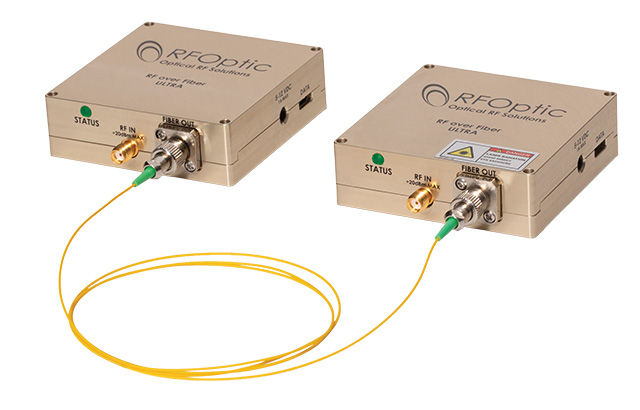
Table of Contents
Introduction
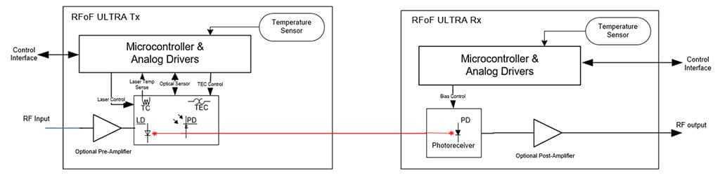
RFOptic’s Ultra RF-over-Fiber compact modules, enable long-distance transport of wideband RF analog signals. The Tx unit is an optical transmitter that modulates wideband RF signals on an optical beam transmitted on an optical fiber to the Rx unit which converts the modulated optical signal back to an RF signal. The single mode fiber that connects the two is generally provided by the customer except for in special application where it is provided as a part of the RFoF link.
In general, a high spurious-free dynamic range (SFDR) is desirable when multiple signals of very different power levels are expected. High IP1dBc (Input power at 1dB gain compression) allows applications to drive the RFoF Ultra RFoF at common application signal levels without additional attenuation. Noise figure may be improved by ordering the RFoF Ultra Tx module with a pre-amplifier. Applications including 5G testing, antenna testing, RADAR and altimeter system testing benefit from high SFDR. The wide dynamic range allows concurrent signals with large amplitude ratios (i.e. between main and side lobes or close and distant targets) to be transmitted with minimal interactions. The same applies to DF/ELINT systems which have to handle strong jammers concurrent with weak signals of interest.
RFOptic’s 12GHz, 20GHz and 20GHz, RFoF Ultra solutions provide high SFDR of 111dB/Hz2/3. Due to their improved IP1dBc higher signal levels can be tolerated and transmitted without distortion. These high-performance products are used in applications such as civil communication, antenna remoting, telemetry, point-to-point, defense systems, satellite communications, and more.
Key Features
- Frequency Range: 0.1GHz – 20GHz
- High IP1dBc
- High SFDR 111dB/Hz2/3
- Excellent Phase Noise
- Excellent phase linearity
- Optical wavelength 1550nm
- Low power consumption
Configurations
- Standard (stand-alone)
- 1U Generic enclosure (8 units)
- 1U Removable panel enclosure (4 units)
- Outdoor (4/8 units)
Applications
- Distributed Antenna
- Satcom
- Radio telescopes
- Telecommunication:
- Antenna Remoting
- Long RF links via fiber
- EW
Options
- Customize RF Gain, P1dB, Noise Figure by adding internal Pre and/or Post amplifier(s)
- Extended low-frequency bandwidth
- DWDM
- Phase matched multi-links
RFoF 20GHz N0 Ultra Specifications
| RF Parameter Tx-Rx Link | Unit | Specification (typical) |
|---|---|---|
| Frequency Range [1] | GHz | 0.1 - 20 |
| RF Gain [2,3] | dB | -29 |
| Gain Flatness [4] | dB | ± 1.8 |
| 1dB input gain compression point [3] | dBm | 24 |
| Noise Figure [2,3] | dB | 41 |
| SFDR (calculated) [3,5] | dB/Hz2/3 | 111 |
| Maximum RF input level (No damage) | dBm | 21 |
| VSWR Input & Output | - | 2:1 |
| Spurious [6] | dBc | <-90 |
| Phase Noise at 10KHz Offset | dBc/Hz | <-130 |
| Input / Output impedance | Ohm | 50 |
| Optical and Electrical and Environmental (Tx, Rx) | ||
| Laser diode optical wavelength | µm | 1.55 |
| Receiver photodiode optical wavelength | µm | 1.1 - 1.65 |
| Operating temperature range | °C | -20 to +70 |
| Storage temperature | °C | -40 to +85 |
| LED status indicators (Tx/Rx) | - | Blue/Green/Red |
| Power voltage | VDC | 5 - 12 |
| Power consumption Tx module [4] | Watt | 0.95 |
| Power consumption Rx module [4] | Watt | 0.25 |
| Mechanical (Tx/Rx) | ||
| Dimensions Tx/Rx unit [7] | mm | 70*70*22 |
| Weight Tx/Rx unit | grams | 220 |
| RF Input / Output connectors | - | SMA |
| Optical Connector | - | FC/APC |
| Power Connector | - | PIN 3.5*1.3*9 mm |
| Data/monitor connector [7] | - | USB-C |
- Extended low frequency 0.02-20.0 GHz is optional.
- Excluding customer fiber loss.
- Gain, P1dB and NF are typical values at 10GHz; Values for configurations with Pre/Post Amps are indicated in the table on page 3.
- Each pre/post amplifier adds about ±1.2dB to the gain flatness, and about 1.8W to the module power consumption.
- Excluding in-band harmonics. SFDR (calculated) ≈ 2/3x[(IP1dB+10) +174-NF] dB/Hz2/3.
- Measured with input signal at Ip1dBc – 3dB at 1GHz.
- See table on page 3 for RFoF Ultra’s Indoor and Outdoor enclosure options.
- For USB monitor, download the software here: https://rfoptic.com/software-download-rfof/ (ask your local representative for the password).
RFoF Ultra 20GHz Module Options
| Parameter | Unit | Ultra 20GHz Transceiver | Ultra 20GHz Transceiver with Pre-Amp | Ultra 20GHz Transceiver with Post-Amp | Ultra 20GHz Transceiver with Pre and Post-Amps |
|---|---|---|---|---|---|
| P/N | - | RFoF-20GHz-N0-Ultra | RFoF-20GHz-A0-Ultra | RFoF-20GHz-A1-Ultra | RFoF-20GHz-A2-Ultra |
| Gain* | dB | -29 | -13 | -13 | 4 |
| Input P1dB* | dBm | 24 | 7 | 24 | 7 |
| Noise Figure* | dB | 41 | 25 | 41 | 26 |
| SFDR* | dBc/Hz | 111 | 110 | 110 | 110 |
* Measured at 10GHz. For Ultra integrated in Indoor/Outdoor enclosures the Gain & P1dB values decrease in about 2dB and NF increase in 2dB.
RFoF 20GHz: Simplified Block Diagram
RFoF Enclosure Options
| Parameter | 19" 1U Enclosure for RFoF | Outdoor Enclosure for RFoF |
|---|---|---|
| Dimensions (mm) | 19" 1U Generic: 445(W)* 476(L)*44(H)19" 1U Removable: 442(W)* 402(L)*44(H) | Small Outdoor: 270(W)*230(L)*85(H) Large Outdoor: 330(W)*350(L)*85(H) |
| RF Input / Output Connector | SMA female | N Type female |
| Optical Connector | FC/APC or SC/APC | MPO/APC 4/8 male [1] |
| Data Connector | USB2/RJ-45 | RJ45 female [2] |
| Power Connector | HP Socket | DC female/ AC male [2,3] |
| Power | 110/220 VAC | 9-36DC / 110/220VAC [2,3] |
- MPO 4/8 optical cable (female) should be ordered by the customer according to the required length and conditions.
- IP-54 Data, AC and DC opposite connectors are provided as accessories with the module (cables are not included).
- DC and AC versions of the outdoor enclosures are available.
Mechanical Outline Drawing: RFoF Ultra 20GHz Tx and Rx modules
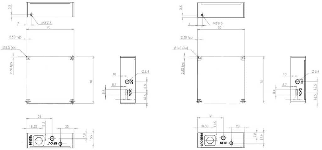
Connector: Positive center plug OD: 3.5mm, ID: 1.3mm, L: 9mm
Ordering Information
| P/N | Description | Tx | Rx |
|---|---|---|---|
| RFoF-20G-N0-Ultra | Transceiver 20GHz, Ultra | RFoF20TFU-N0-11 | RFoF20RFU-N0-11 |
| RFoF-20G-A0- Ultra | Transceiver 20GHz, Ultra with Pre-Amp | RFoF20TFU-A0-11 | RFoF20RFU-N0-11 |
| RFoF-20G-A1- Ultra | Transceiver 20GHz, Ultra, with Post-Amp | RFoF20TFU-N0-11 | RFoF20RFU-A0-11 |
| RFoF-20G-A2- Ultra | Transceiver 20GHz, Ultra with Pre and Post-Amp | RFoF20TFU-A0-11 | RFoF20RFU-A0-11 |
Contact information: Tel. Int.: +972-76-540 0180, Tel. USA: +1 708 RFOPTIC, To contact us directly, click here