

Programmable 3GHz Bidirectional RF over Fiber
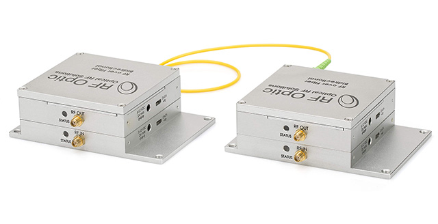
Table of Contents
Introduction
RFOptic bidirectional RF over Fiber (RFoF) link is an innovative compact 2-way transceiver. It is comprised of an uplink of Tx and Rx (at 1550nm) and a downlink of Tx and Rx at 1310nm. The transceiver employs WDM technology to allow it to use only one fiber link instead of two fibers for transmission over long distances. Each terminal contains an optical transmitter (Tx) converts RF to the optical signal and an optical receiver unit converts back to the RF signal (Rx). The two terminals are connected through the customer’s single mode fiber to complete the bidirectional RFoF link.
RFOptic’s bidirectional (RFoF) modules are suitable for telecommunications, WIFI, radio and other types of systems which require communication in both directions. For example, point-to-point antennas can be connected using fibers that are several meters to many kilometers long reaching from an equipment shelter or control room to an antenna on a tower. Base stations can be connected through fiber to remote sector antennas or DAS systems which provide extended coverage.
Both the Tx and Rx units include amplifiers and variable attenuators that enable adjustment of the Noise Figure, Input P1dB, and Gain over wide range of values. The LNA in the Tx units can be activated through the RFOptic Configuration software. When active it brings the noise figure (NF) to below 6dB allowing very low RF input signals to be transmitted. The RFoF link has excellent gain flatness with 0.5dB gain tracking between different links. For special applications requiring temperature stability operation, a unique algorithm supporting ±1dB over 100° C can be activated. The DC power of the RFoF modules is flexible from 5 to 12 Volts.
The RFOptic Configuration software enables adjustment of the RF and Optical parameters, such as link gain, Noise Figure, P1dB, Optical power, LED indication and delivers module status information, either locally or remotely.
Furthermore, the RFoF link has full diagnostic capability, including Tx, Rx, and complete link test (Optical and RF). These features save the cost of test equipment and provide real-time diagnostics of any deployed link.
Key Features
- Next generation RFoF modules with significant performances improvement.
- Available frequency coverage versions: 1MHz to 2.5GHz, 3GHz, 4GHz and 6GHz.
- Utilizes WDM technology.
- Better linearity, excellent gain flatness, and Tx, Rx and Link gain control.
- Noise Figure down to 6 dB with LNA.
- Internal microcontroller allows RF and Optical setup and control, enabled by software.
- End-to-end diagnostics reduces installation and maintenance time, enabled by software.
- Gain variation S21 of ±1 dB over 90°C temperature variation, utilizing special algorithm.
- Remote management by GUI installed on PC.
- Supports 50 Ohms and 75 Ohm Impedances.
Configurations
- Outdoor enclosure (unidirectional / bidirectional)
- 1U Generic enclosure
- Standalone unit.
Applications
- Remote Antennas Communication
- Satcom
- 4G LTE
- Broadcast
Programmable 3GHz Bidirectional RF over Fiber specifications (example)
| Electrical | Unit | Specification (typical) LNA “OFF” | Specification (typical) LNA “ON” |
|---|---|---|---|
| Frequency Range | MHz | 1 - 3000 | 1 - 3000 |
| Adjustable Link Gain (nominal value) [1] | dB | 12 | 42 |
| Step Attenuator 31.5dB (Tx, Rx) [2] | dB | 0.5 | 0.5 |
| Gain Flatness | dB | ±1.5 | ±1.5 |
| Input P1dB [3] | dBm | -3 | -33 |
| Noise Figure [3] | dB | 23 | 6.5 |
| SFDR [3] | dB/Hz2/3 | 104 | 100 |
| Uncorrected gain variation over temperature | dB | ±3.5 | ±3.5 |
| Corrected gain variation over temperature [4] | dB | ±1.5 | ±1.5 |
| Corrected gain tracking between RFoF links [5] | dBm | ±0.5 | ±0.5 |
| Maximum Input No damage | dBm | 20 | 20 |
| VSWR Input / Output | dBm | 1.7:1 | 1.7:1 |
| Input / Output impedance [6] | Ohm | 50 | 50 |
| Optical and Electrical | 0.5 - 3000 | ||
| Power | VDC | 5 - 12 | 5 - 12 |
| Current consumption of Tx unit (at 5VDC) | mA | 260 | 385 |
| Current consumption of Rx unit (at 5VDC) | mA | 225 | 225 |
| Laser diode wavelength | µm | 1.31 and 1.55 | 1.31 and 1.55 |
| Optical Power in the fiber | mw | 2.3 ±0.5 | 2.3 ±0.5 |
| LED status indicators (Tx/Rx) | - | RGB | RGB |
| Mechanical and Environmental Parameters | |||
| Operating temperature | °C | -20 to +70 | -20 to +70 |
| Storage temperature | °C | -40 to +85 | -40 to +85 |
| Size | mm | 130x90x40 | 130x90x40 |
| EMC and Safety [7] | - | CE & FCC | CE & FCC |
| DC Connector: Positive center plug OD: 3.5mm, ID: 1.3mm, L: 9mm | |||
| Data Connector [8] | Micro USB | ||
- LNA ‘ON’ or ‘OFF’ is selected by RFOptic manufacturing, or by using the RFoF user software.
- ‘No Attenuation’ is the default for Tx and Rx units. Attenuation values can be selected by the user software.
- Noise Figure, Input P1 dB, Input IP3 and SFDR measured at 1.5GHz, can be selected by ‘LNA Off/ON’ and Tx Attenuator.
- Using internal temperature compensation algorithm selected by the user software.
- Using the Tx and/or Rx Attenuators.
- 75 Ohm is optional with similar VSWR, by using SMA/BNC adaptor.
- Safety EN60950-1:2006(2nd); EMC: ETSI EN 300 386 v1.6.1 (2012-04) and FCC CFR-47 part 15 Sub part B.
- For USB control, download software here: rfoptic.com/software-download-rfof/ (ask your local representative for the password)
Programmable 3GHz RFoF: Simplified Block Diagram

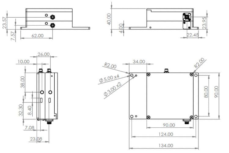
Mechanical Outline Drawing: Programmable Bidirectional RFoF units
Ordering Information
| Part Number | Product Description |
|---|---|
| RFoF-2G-5531S-B1 | 2.5 GHz 1550 & 1310 Tx and two Rx units with one SM Fiber and Mux, SC/APC, Programmable |
| RFoF-3G-5531S-B1 | 3.0 GHz 1550 & 1310 Tx and two Rx units with one SM Fiber and Mux, SC/APC, Programmable |
| RFoF-4G-5531S-B1 | 4.0 GHz 1550 & 1310 Tx and two Rx units with one SM Fiber and Mux, SC/APC, Programmable |
| RFoF-6G-5531S-B1 | 6.0 GHz 1550 & 1310 Tx and two Rx units with one SM Fiber and Mux, SC/APC, Programmable |
| RFoF- AC-DC-Programmable | Four 220/110 AC/5VDC converters for programmable bidirectional RFoF |
Contact information: Tel. Int.: +972-76-540 0180, Tel. USA: +1 708 RFOPTIC, To contact us directly, click here