

Programmable 4.0GHz RF over Fiber
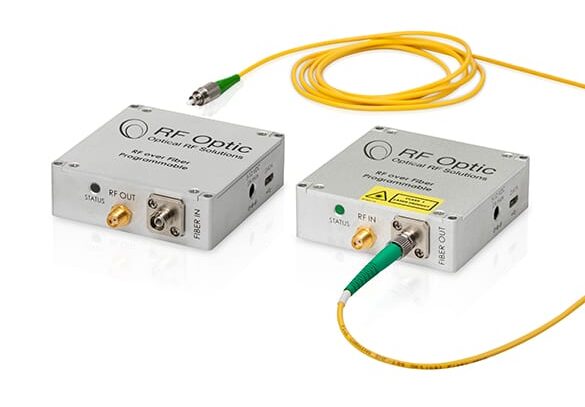
Table of Contents
Introduction
RFOptic’s innovative controllable RFoF product line consists of palm-size, analog, RFoF modules used for long distance, low noise transmission of RF signals over an optical fiber. The Tx unit’s optical transmitter converts the RF to an RFoF optical signal; the Rx unit converts the received RFoF Optical signal back to RF. The two units are connected by a single mode fiber.
RFOptic’s RF over Fiber (RFoF) modules are suitable for telecommunications, satellite, radio telescopes, distribution antennas, audio and video broadcasting, and timing synchronization. For example, point-to-point antennas can be connected over distances of several meters to tens of kilometers over fiber cables; base stations can be connected over fiber to remote sector antennas, and satellite antennas can be connected to remote sites by RF over Fiber solutions.
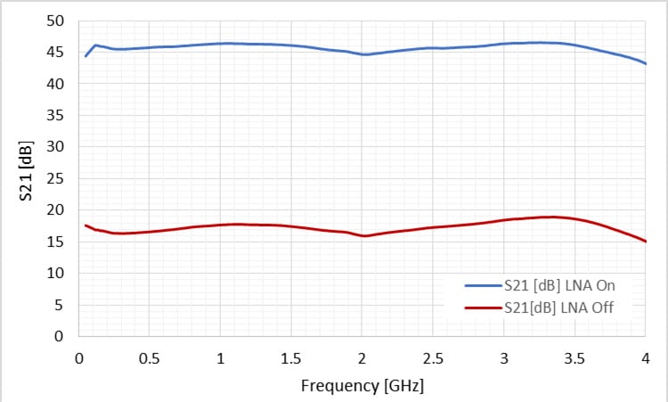
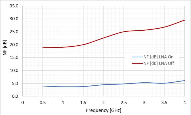
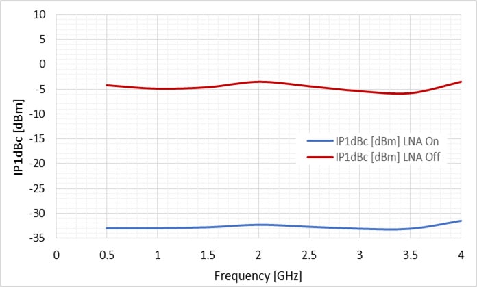
Both Tx and Rx units include LNAs and variable attenuators enabling you to adjust Noise Figure, Input P1dB, and IP3 over wide dynamic ranges. The LNA can be activated via RFoF software enabling RF input power below -100dBm/1MHz and a Noise Figure of 5dB for low signal applications.
The RFoF link has excellent gain flatness and features 0.5dB gain tracking between links. For special applications requiring temperature stability operation, RFOptic has developed a unique algorithm supporting ±1dB gain variation over a 100°C temperature range. RFoF modules operate with flexible DC power of 5—12VDC.
User-friendly RFoF software enables adjustment of the RF and optical parameters (such as link gain, Noise Figure, P1dB) and provides optical power, LED indication and module information over a driverless USB connection.
In addition, the RFoF link has full diagnostic capability, including Tx, Rx, and complete link testing (optical and RF). These features save the cost of test equipment and provide real-time diagnostics of any deployed link.
The link gain calculator enables you to calculate link gain and predict optical parameters for the entire family of RFOptic’s programmable, RFoF products.
Key Features
- Supports 1MHz — 4.0GHz.
- Better linearity, excellent gain flatness, Tx, Rx, and link gain control.
- 5dB LNA Noise figure, -169dBm/Hz MDS for very low incoming signals.
- Excellent Phase Noise
- Internal microcontroller allows RF and optical control, via software.
- Software controlled, end-to-end diagnostics reduces installation and maintenance time.
- Local management via PC GUI.
Options
- CWDM channels
- Proprietary algorithm enables gain variation of
- ±1dB for 100°C temperature variation.
- Automatic Level Control (ALC) via proprietary algorithm.
- Remote management and control (M&C) via HTML/REST/SNMP interface (RJ45) for RFoF units installed in enclosures.
Configurations
- Standalone RFoF Tx/Rx units
- Unidirectional/Bidirectional configurations
- 19” 1U Generic enclosure (up to 8 RFoF units)
- 19” 1U Removable enclosure (up to 4 RFoF units)
- 19” 2U Removable enclosure (up to 8 RFoF units)
- 19” HD enclosure (up to 40 RFoF units/20 Bidirectional terminals)
- Mini RFoF enclosure (up to 2 RFoF units)
- Small outdoor enclosure (up to 4 RFoF units)
- Large outdoor enclosure (up to 8 RFoF units)
Applications
- Remote Antennas
- 4G LTE, GSM
- Distributed Antenna
- Broadcast
- Satcom
Programmable 4.0GHz RF over Fiber specifications
| Electrical | Unit | Specification (typical) LNA “OFF” | Specification (typical) LNA “ON” |
|---|---|---|---|
| Frequency Range | MHz | 1 — 4000 | 1 — 4000 |
| Adjustable Link Gain (nominal value) [1] | dB | 12 | 42 |
| Attenuator 31 dB (Tx, Rx) [2] | dB | 0.5 | 0.5 |
| Gain Flatness | dB | ±2.0 | ±2.0 |
| Input P1 dB [3] | dBm | -3 | -33 |
| Noise Figure [3] | dB | 23 | 6.5 |
| SFDR [3] | dB/Hz2/3 | 104 | 100 |
| Uncorrected gain variation over temperature | dB | ±3.5 | ±3.5 |
| Corrected gain variation over temperature [4] | dB | ±1.5 | ±1.5 |
| Corrected gain tracking between RFoF links [5] | dB | ±0.5 | ±0.5 |
| Maximum Input No damage | dBm | 20 | 20 |
| Spurious (input signal at Ip1dBc - 3dB at 1GHz) [6] | dBc | -85 | -75 |
| Phase Noise at 4GHz at 10KHz Offset | dBc/Hz | -145 | - |
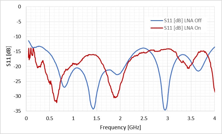
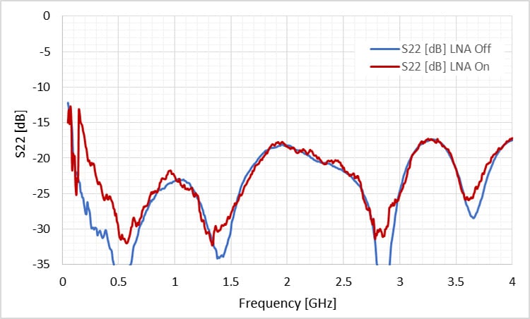
| VSWR Input / Output | dBm | 1.7:1 | 1.7:1 |
| Input / Output impedance [7] | Ohm | 50 | 50 |
| Optical and Electrical | |||
| Current consumption of Tx unit (at 5VDC) | mA | 260 | 385 |
| Current consumption of Rx unit (at 5VDC) | mA | 225 | 225 |
| Laser diode wavelength | µm | 1.31 or 1.55 | 1.31 or 1.55 |
| Optical Power in the fiber | mw | 2.3 ±0.5 | 2.3 ±0.5 |
| LED status indicators (Tx/Rx) | - | RGB | RGB |
| Mechanical and Environmental Parameters | |||
| Operating temperature [8] | °C | -20 — 70 | -20 — 70 |
| Storage temperature | °C | -40 — 85 | -40 — 85 |
| EMC and Safety [9] | — | CE & FCC | CE & FCC |
RFoF 4.0GHz module options
| Parameter | RFoF Tx/Rx Units | 19" 1U Enclosure for RFoF | RFoF 4.0GHz Outdoor |
|---|---|---|---|
| Dimensions (mm) | 70(W)*70(L)*22(H) | 19" 1U Generic: 445(W)*476(L)*44(H)19" 19" 1/2U Removable: 442(W)*402(L)*44(H) | Big Outdoor: 330(W)*350(L)*85(H) Small Outdoor: 270(W)*230(L)*85(H) |
| Number of units | — | Up to 8 Up to 4 | Up to 6 Up to 4 |
| RF I/O Connector | SMA female | SMA female | N Type female |
| Optical Connector | FC/APC or SC/APC | FC/APC or SC/APC | MPO/APC 4/8 male [10] |
| Data Connector | Micro USB | USB2/RJ45[14] | RJ45 female [11] |
| Power Connector | PIN 3.5*1.3*9 mm | HP Socket [13] | DC female/ AC male [11,12] |
| Power | 5—12 VDC | 110 / 220 VAC | 9—36 VDC / 110 / 220VAC |
- LNA ‘ON’ or ‘OFF’ is factory set by RFOptic or by using RFoF user software.
- ‘No Attenuation’ is the default setting for Tx & Rx units. Attenuation values of 0 — 31dB in 0.5dB steps can be selected via the user software.
- Noise Figure, Input P1 dB, Input IP3, and SFDR (measured at 1.5GHz), can be selected by ‘LNA Off/ON’ and the Tx Attenuator.
- Using the software’s internal temperature compensation algorithm.
- Using the Tx and/or Rx Attenuators.
- LNA On: Tx pre-amplifier gain of +31dB.
- 75Ω impedance is optional using the SMA/BNC adaptor.
- RFoF units for (-)40°C — 85°C are available.
- Safety EN60950-1:2006(2nd); EMC: ETSI EN 300 386 v1.6.1 (2012-04) and FCC CFR-47-part 15 Sub part B..
- Customer should order the MPO 4/8 optical cable (female) customer according to required length and conditions. Example: GoFoton: P/N BPF3P1SM015FLR020 (4 fibers)/BPF3P1FM015FLR021 (8 fibers). XXX = 15m fiber length.
- IP-54 Data, AC and DC opposite connectors are provided as accessories with the module (cables are not included).
- DC and AC versions of the outdoor enclosures are available.
- 2 cable clamps to secure the RFoF Tx/Rx units’ power adapter cables are provided.
- For USB control, download software here: rfoptic.com/software-download-rfof/ (Ask your local representative for password.)
Programmable 4.0GHz RFoF – Simplified Block Diagram
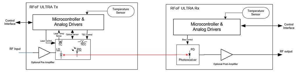
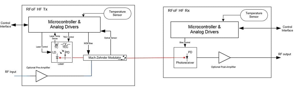

Programmable 4.0GHz RFoF: Simplified Block Diagram
Mechanical Outline Drawing: Programmable 4.0GHz RFoF Rx & Tx units
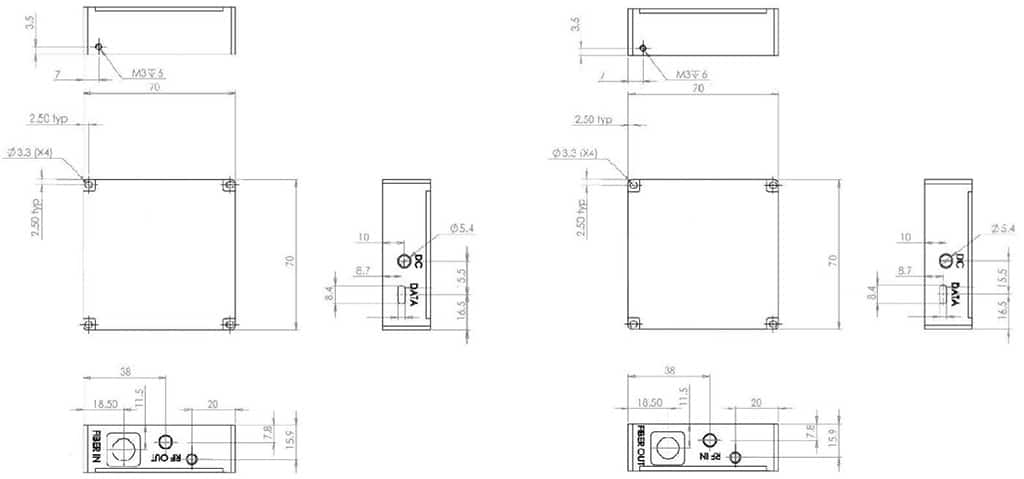
Connector: Positive center plug OD: 3.5mm, ID: 1.3mm, L: 9mm
Ordering Information
| Part Number | Product Description | Tx | Rx |
|---|---|---|---|
| RFoF-4.0GHz-1310-Prog | 4.0GHz Transceiver 1310, FC/APC, Programmable | RFoF4T3FR-PA-11 | RFoF4R3FR-PA-11 |
| RFoF-4.0GHz-1550-Prog | 4.0GHz Transceiver 1550, FC/APC, Programmable | RFoF4T5FR-PA-11 | RFoF4R5FR-PA-11 |
| RFoF-AC-DC-Prog | 2*220/110 AC/5VDC adapter for Programmable* | — | — |
| RFoF-AC-DC-Prog-1 | 1*220/110 AC/5VDC adapter for Programmable | — | — |
* Each RFoF module requires one AC/DC adapter, therefore two (2) adapters are needed for a link.
Options
- For outdoor or rack mount options, please contact RFOptic
- SC/APC optical connector is optional
Contact information: Tel. Int.: +972-76-540 0180, Tel. USA: +1 708 RFOPTIC, To contact us directly, click here